
LFEX Petawatt Laser
Background
The first phase of the FIREX (Fast Ignition Realization Experiment), referred to as FIREX-1, was drawn up with the aim of enhancing and refining existing heating lasers in order to heat fusion fuels up to 5–10 keV, the temperature range required for nuclear fusion. Consequently, construction of the heating LFEX (Laser for Fast Ignition Experiment) [2] began in the fiscal year 2003. The laser was designed to meet the following specifications: an output of 10 kJ in a 1–10 ps pulse width; a wavelength of 1.05 μm; a cone-focused spot diameter of 30 μmφ. As such, the LFEX is a unique, ultra-high intensity laser, and is expected to be applied to experiments relating not only to nuclear fusion, but also to relativistic plasma interactions and laser-induced nuclear physics
Oscillator and amplification unit [3]
Initially, seed light from a femtosecond fiber oscillator with a suitable spectral band (90 fs, 100 MHz, electrically synchronized) is amplified by three-stage optical parametric amplification (OPCPA), yielding a chirped light output with an energy of at least 40 mJ, and a spectral width of 6 nm at 6 Hz. Then, the diameter is expanded from 10 mm to 25 mm, and the light is four-pass amplified by two glass rod amplifiers (diameter 50 mm). Furthermore, the light is branched into four beams, where each beam is amplified by each of two rod amplifiers and then directed into the main amplifier. The main amplifier is an amplifier composed of eight units connected in series; each unit contains laser glass slabs (LHG8, 46 cm × 81 cm × 4 cm) arranged in a 2 × 2 array structure (Fig. 1). The maximum aperture size is 40 cm × 40 cm, and the resulting beam size is 35 cm × 35 cm.
After four-pass amplification, the laser light is then reflected by the end mirror and directed into a Faraday rotator, where the polarization is rotated. The Faraday rotator is combined with a thin-film polarizer to form an optical isolator to protect the amplifier from the light reflected off the target irradiated by a focused beam.
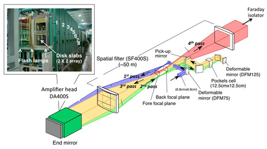
Fig. 1 Configuration of the main amplification section of LFEX
Beam transport, compression, and focusing optics
Fig. 2 shows a general overview of the pulse compressor and focusing optics in the rear end of LFEX. The 2 × 2 beam arrays from the front end are re-constructed into vertical (1 × 4) arrays and are then directed into a diamond-shaped pulse compressor [4, 5]. To account for the 72° angle of incidence and the beam broadening that occurs due to chromatic dispersion, a composite diffraction grating consisting of two 42 cm × 91 cm diffraction gratings (1740 grooves / mm) is used for each beam. As the pulse compressor is image-inverting (the composite diffraction grating is used from both sides), both the phase and alignment errors of the individual diffraction gratings are automatically canceled out. The pulse-compressed beam is subsequently re-constructed into a 2 × 2 array and focused by an OAP (off-axis parabolic mirror, 104 cm × 89 cm, F/~5). The first light was achieved with one beam in February 2008, and construction is currently underway to upgrade LFEX to a four-beam system: as of June 2012, two beams have been used to achieve light with a pulse width of 2.2 ps and a focused diameter of about 50 mm on a target.
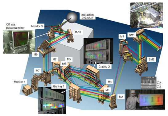
Fig. 2 Configuration of the pulse compressor and beam-focusing optics of LFEX
Optical elements
The composite diffraction grating is constructed from two gratings in order to achieve the width for a 42 cm square aperture and a total length of about 1.8 m. Some of the basic technologies necessary for manufacturing these large-diameter optical elements are described in this section.
Wavefront measurement instruments (interferometers) suitable for wavelengths of around 1 μm and the dimensions given above were developed in a joint venture between companies in Japan and the United States. This instrument can make measurements in areas of up to 70 cm in diameter, making it one of the world’s greatest 1 μm wavelength interferometers.
Quartz, which exhibits low thermal expansion properties, is used as the substrate for the optical elements. In order to prevent film cracking (crazing), an evaporation device based on ion-assisted deposition (IAD) was jointly developed in a collaboration between Japan and the US, enabling deposition of films with strong substrate adhesion, even under low-temperature growth conditions.
The focusing mirror is an 89 cm × 104 cm OAP with good light focusing properties.
In the development of the composite diffraction grating, a scanning interference exposure method was developed and adopted. In this method, the groove density of the diffraction grating can be controlled to an accuracy of an order higher than by conventional methods; additionally, the overall size of the diffraction grating can be made larger than with conventional methods [6]. A US-Japan collaboration was established for the fabrication of the diffraction gratings, where the quartz substrate polishing and IAD film synthesis were carried out in Japan, and the ruling (groove formation) was carried out in the US by a start-up company [7]. A photograph of one of the diffraction gratings that were successfully mass produced is shown in Fig. 3. These diffraction gratings have achieved several milestones, such as the world’s largest dimensions, a groove density reproducibility one order higher than that of conventional gratings, a maximum diffraction efficiency of 98 %, and high damage resistance.
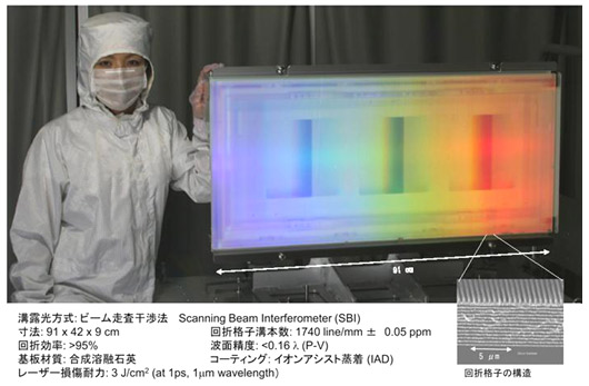
Fig. 3 World’s largest dielectric diffraction grating on a quartz substrate (104 cm x 89 cm)
References
- Yoshiki Nakata, Hiroyuki Shiraga, Junji Kawanaka, Takahisa Jitsuno, Noriaki Miyanaga, OPTRONICS, vol. 31, 130 (2012).
- N.Miyanaga, et al., EDP Sciences, J. de Physique IV 133, 81 (2006).
- J.Kawanaka, et. al., J. of Phys.: Conf. Series, The fifth International Conference on Inertial Fusion Sciences and Applications (IFSA 2007), 112, 032006 (2008).
- H.Habara, et al., Opt. Lett., 35, 1783 (2010).
- M.C. Rushford, J. A. Britten, C. P. J. Barty, T. Jitsuno, K. Kondo, N. Miyanaga, K. A. Tanaka, and G. Xu, Opt. Lett. 33, 1902 (2008).
- M.H. Lim et al., J. Vac. Sci. Technol. B 17, 2703 (1999).
- Takahisa Jitsuno, Shinji Motokoshi, Journal of Japan Laser Processing Society 12, 221 (2005).